Ignition System
With the exception of the spark plugs and plug wires, all of the ignition system is located under the flywheel. The type of magneto ignition on this motor is Flywheel Magneto with Breaker Points. OMC used the same Universal Magneto on most of their small outboards from the 50's up until recently when they started using electronic ignitions. The job of the ignition system is to generate enough voltage (around 20,000 volts) to jump the gap on the spark plugs, creating a spark and igniting the fuel/air mixture, and to make sure that voltage is delivered to the spark plug with exactly the right timing.
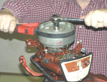
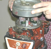
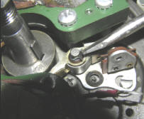
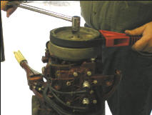
Remove the Flywheel Nut - Loosen the flywheel nut. Using a 3/4 inch socket or another wrench, loosen the flywheel nut. You will need something to hold the flywheel stationary so that you can apply torque to the nut while holding the flywheel so it will not turn with the nut. There are special tools for this but I used a Strap Wrench that someone gave me for Christmas a couple years ago. I've read where sometimes people will stick a piece of rope in the spark plug hole so the piston will be stopped before reaching Top Dead Center, therefore, holding the flywheel in place so you can remove the nut. I believe this might damage the engine internally by putting too much pressure on the connecting rods. Also, I've read on discussion boards that the rope can become cut off leaving a piece of rope in the cylinder
|
|
.Remove the Flywheel - There are two ways to remove the flywheel, depending on the tools you have. Most mechanics will recommend that you use a flywheel puller. You can rent a steering wheel puller from your local tool rental shop or you can buy a harmonic balancer. Using a puller is the safest way to prevent bending or warping the flywheel. You want a puller that attaches to the three bolt holes in the flywheel to remove it. Do not use a puller that pulls up on the outer edge of the flywheel.
|
|
|
|
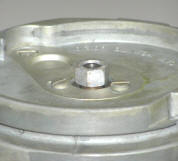
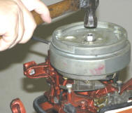
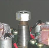
The other, more field expedient way to pull the flywheel is to simply loosen the flywheel nut to where it is slightly above the crankshaft. With a large flat head screwdriver and a soft hammer, lightly tap downward on the flywheel nut while prying upward on the bottom edge of the flywheel with the screwdriver. Make sure you are prying upward on the flywheel itself by making sure that it is the part that spins and not a part that is stationary. Turn the flywheel 1/4 turn and tap again and repeat until the flywheel is loose. The flywheel should come loose after a few taps and can be lifted off the crankshaft after removing the flywheel nut. The danger in this method is that if you tap too hard with the hammer you could break the crankshaft.
Replace Ignition Parts
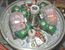
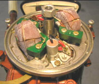
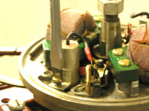
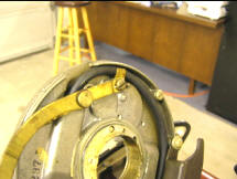
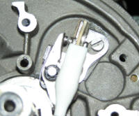
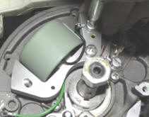
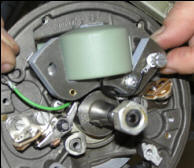
The ignition parts located under the flywheel which consists of points, condensers, and coils, two of each because there are two cylinders. Over time, these components deteriorate and need replacing. You can see from the picture below that the epoxy that covers the coil windings is completely cracked. This is a common problem with old OMC motors. Without replacement, any moisture around the engine will cause the coils to short or arc over which will cause your to spark plugs not to get a good spark so that the motor will run well, especially at high speed. Probably 9 out of 10 of these motors that exist today have coils in the same condition as those shown below. New coils are superior to the original OEM because have a different epoxy sealer that will not have this problem. The new points, condensers, and coils are far superior quality and performing that the originals. The parts are widely available and fairly inexpensive.
Ignition Parts Needed
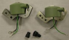
Coils (you need 2 of these) OMC Part Number 582995 or 584477, NAPA/Sierra Part Number 18-5181
Help support this site: Click HERE and buy it on Amazon.com
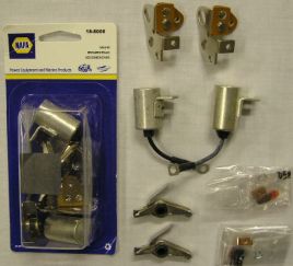
Ignition Tune-Up Kit OMC Part Number 172522 NAPA/Sierra Part Number 18-5006
Help support this site: Click HERE and buy it on Amazon.com
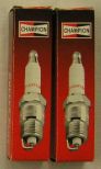
Spark Plugs Champion J6C
Help support this site: Click HERE and buy it on Amazon.com
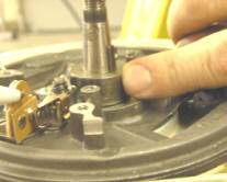
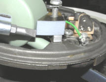
Remove the Old Coils - Each coil is held in place by one phillips and two straight head screws. Be sure to use the proper size screwdrivers on these screws so they do not become damaged. Once the screws are removed, disconnect the green and black primary wires and twist off the spark plug wire.
|
|
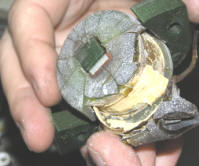
These old coils completely fell apart during the removal process.
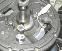
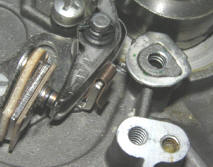
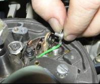
Remove the Old Points and Condensers - Remove the retainer clip at the top of the rocker post. Once the clip is removed, you can remove the moveable half of the points by pulling it up and off the rocker post.
|
|
|
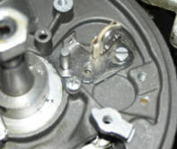
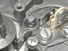
Next, remove the non-moveable half of the points. Do not remove the adjusting screw. The adjusting screw does not attach the points to the stator plate and should not be removed. The adjusting screw is the screw that is smaller and farthest from the crankshaft and fits within an elongated slot in the points. Unscrew the screw that holds down the base of the points. This is the screw that is located closest to the crankshaft. Unscrew and remove the coil and condenser wires that are attached to the points. You may also remove the condenser.
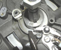
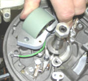
Remove and Clean the Stator Base - Using carburetor cleaner, spray down the stator base and wipe clean with a cloth. If you have compressed air, blow off any remaining dust and carburetor cleaner.

|
|
|
Now that you have your coils, points, and condensers removed and your stator base cleaned up, you are ready to reassemble the ignition system with new parts.
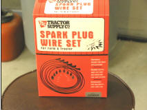
Inspect Spark Plug Wires and Replace if Necessary - While you have your stator base off, it is a good time to inspect your spark plug wires for any time of wear or corrosion. In my case, the ends of my plug wires were corroded so I felt it was a good opportunity to replace the spark plug wires. After much shopping around, I found out that the generic 22-inch plug wires sold at NAPA were not long enough. I wound up going to a place called Tractor Supply and bought a set of 4 spark plug wires for around $10. Note that there is a difference between the older "solid core" wires used on antique cars and boat motors and the newer "carbon core" wires used on today's automobiles which cut down on electronic emissions which cause interference with radios and such. You definitely need to solid core wires on these motors. Using the old spark plug wires as a pattern and allowing an extra inch of length, I cut the new wires to length and routed them around the same path on the bottom of the stator plate. I don't know what the rule for replacing spark plug wires is but I figure after over 50 years, they need to be replaced! I've been told that most boat and lawnmower repair places have this type of solid core wire on bulk rolls and can cut off the length you need, put on some boot caps and I am sure they will work well.
Install, Set, and Test the New Points - If you want your motor to run well, your points must be installed, set, and tested to be sure that they open and close at precisely the right time. This determines when your spark plugs will fire, setting off the combustion within your cylinders. You will be able to tell exactly when your points are set correctly by testing them with a couple test leads and an ohm meter.
|
|
|
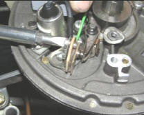
Feed one end of a test lead up through the bottom of the stator base next to one of your spark plug wires. This will be used for testing and will be removed after the points are adjusted and tested. Feed one end of a test lead up through the bottom of the stator base next to one of your spark plug wires. This will be used for testing and will be removed after the points are adjusted and tested.
|
|
|
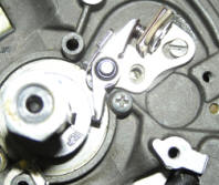
Lubricate both rocker posts with the grease provided in your ignition tune up kit. Be sure to put only a thin coat of grease on the rocker posts. Lubricate the cam with by placing a small amount of the grease provided with the points onto your finger and rubbing a small coating onto the cam while turning the crankshaft. One easy way to turn the crankshaft on this motor is to simply reach down with one hand and turn the propeller. Place the non-movable side of set of points onto the armature base by placing it over the adjusting screw and positioning it so you can install the mounting screw. Install the mounting screw and lock washer. Place the moveable side of the new points set over the pivot post and press into position. You will need to compress the spring so that it will fit inside the flat piece of metal. Place the retaining clip onto the pivot post and orient it so that it opens away from the crankshaft. Place the spring retainer clip over the spring and the flat piece of metal that holds the spring tension. Make sure the the flair on the bottom of this clip is pointed away from the breaker arm so that it will not interfere with the opening of the points.
|
|
|
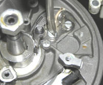
Turn the crankshaft so that the breaker arm rubbing block is on the high point of the cam. The high point on the cam has the word "TOP" stamped at the high point location. Using a feeler gauge, adjust the gap to .020 inch by turning the adjusting screw. The feeler gage .020 blade should be able to snugly fit between the two contact points. There is no need to spend too much time getting 020 gap exact. This .020 gap is simply a starting point from which to adjust from as you will see in the procedure below. Clip one end of your test leade to the location where the coil and condenser wire will be screwed to the points.
|
|
A simple but effective method to test the ignition timing: If you do not have a strobe light or an expensive ignition analyzer to check your breaker points, there is no need to rush out to the store and buy one. All you need to test your ignition timing is two alligator test leads and a common ohm meter to check continuity. There is no need to use an ignition analyzer because all your ignition parts are new. This method will allow you to adjust your ignition timing just as accurately as you can with the more expensive test equipment. Ignition timing is all about making sure your breaker points are opening and closing at the right time. The instructions stamped on the top of the flywheel and service manuals simply say to gap your points to .030 inch. This is only an approximation and may or may not result in your ignition timing being correct. If you will use the method described below, your timing will be exact and the end result will be that your motor will run more smoothly and start easier.
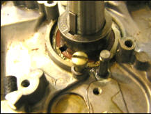
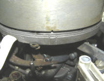
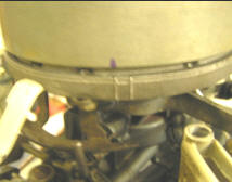
Remove the flywheel nut and temporarily replace the flywheel back onto the crankshaft. Be sure that the slot in the center of the flywheel fits over the flywheel key and the flywheel is locked into position. Replace the flywheel nut without tightening it. The flywheel has timing notches at its base. There are two notches on opposite sides of the flywheel, one for each set of points. The larger notch will be for cylinder number one and the smaller notch on the opposite side is for cylinder number two. Take a Sharpie marking pen and highlight these marks so they will be easily visible.
|
|
|
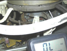
Connect the loose end of your test lead to one of the leads on your ohm meter. Connect the other lead of your ohmmeter to ground with another test lead. As you rotate your flywheel clockwise, watch the timing mark as it nears the two marks on the armature base. The mark on the flywheel should be moving from right to left as you rotate the flywheel. When the timing mark on the flywheel is between the two marks on the armature plate, the points should open and the ohm meter will change from 0 to infinite ohms. In this type of magneto ignition, the spark plug will fire as the points open.
If the gap in the points is too small, the points will open late or after the timing mark passes the marks on the armature base. If gap in the points is too wide, the points will open early or before the timing mark reaches the marks on the armature base. This motor has a small metal cover in the top of the flywheel that you can remove and access the gap adjustment screws to open or close the gap in the points. Make small adjustments to the gap adjustment screw until you get the points to open when the timing mark is between the two marks on the armature base.
Now install, set, and test the second set of points, except this time, you will use the smaller timing mark on the opposite side of the flywheel. Also, you can skip the lubrication of the cam and rocker post that you did with the first set of breaker points.
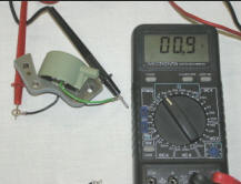
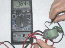
Test the New Coils - Don't assume that the new coils you bought are good. Using an Ohmmeter or a Diode Continuity Checker test the continuity of the primary windings of the coil. There should be continuity between the Green and Black leads. There should be about .9 ohm resistance between the Green and Black leads.
|
|
Install New Coils and Condensers
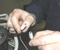
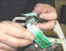
Put a small amount of silicone compound in the hole for the spark plug connector. This is not the kind of silicone that you use to seal your bathtub. This kind of silicone sealer does not harden. It serves to keep moisture out of your electrical connection. You can buy this silicone sealer at any Radio Shack or electronics store. Slide the spark plug wire boots onto your spark plug wire.
|
|
|
The spark plug wire is connected to the coil by screwing it onto a threaded pin. You may need to loosen the screw holding the spark plug wire so you will have enough slack to screw them into the connector. Screw the spark plug into its connector and slide the boot over the connector. This should provide a good waterproof seal for this connection. Rotate the coil into place aligning the screw holes. Tighten the screw holding the spark plug wires on the bottom side of the armature plate.
|

|
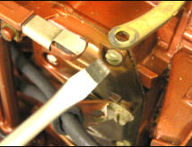
The black wire of the coil is grounded by connecting it to the coil mounting screw that is farthest away from the points. The pictures above show the wrong and right way to route this coil ground wire. You want to make sure the all wires are tucked neatly away so they will not touch any moving parts. In the case of this coil, I tucked the black wire in behind the Phillips head mounting screw. Also, you want to make sure that no wires get pinched and they have a little slack so they will not put stress on their connectors.
Before you tighten the mounting screws, make sure that the coil magnet does not extend past the mounting block at the base of the armature. If the coil is positioned so the magnet extends past this base, the coil magnet will touch the inside surface of the flywheel.
|
|
|
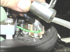
Loosely connect the green coil wire and also the black condenser wire to the points. Mount the condenser to the base with it's mounting screw. Tighten the screw holding condenser and coil wire. Be careful not to over-tighten this screw or push against the points because this can mess up your adjusted points.
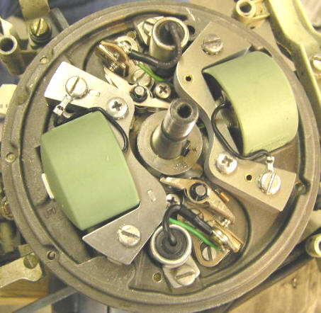
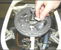
Your finished Ignition System should look like this.
Replace the flywheel and snugly tighten the flywheel nut. If you have a torque wrench, torque the flywheel nut to about 45 foot pounds.
Check for Spark - Remove the old spark plugs. Using a pair of needle-nose pliers, straighten the end of the old spark plugs and reconnect the old plugs to their wires. While holding the base of the old spark plugs to ground, rotate the flywheel clockwise either by hand or by turning on the flywheel nut with a wrench. You should see a healthy spark jumping the gap of your old plugs.

Gap and Install New Spark Plugs - Using a feeler gauge, adjust the gap of your new spark plugs to .030 inch. The new plugs will not come out of the box with the correct gap and gap the plugs is a simple procedure that is often overlooked. If you do not have a special tool for adjusting the spark plug gap, you can use a knife blade to widen the gap or lightly tap the end of the plug with something hard to close the gap. Install the new spark plugs and your ignition system is tuned-up.